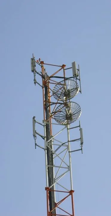
"VEGA Dual Array ultra-high gain BTS antenna
for ultra-high gain cellular applications"
1. Introduction
VEGA (Very High Gain Antenna) very high gain, narrow beam dual polarization dish antenna specifically designed for cellular BTS applications.
"At cellular frequency bands 780–960 mHz VEGA CC-12 models offer the cellular planner a beam width of 11˚ in both azimuth and elevation patterns and gain of +23dBi."
VEGA antenna itself has a gain 5-7 dB higher than most common sector panel antennas.
For certain unique applications, where there is a need for an even higher gain of about+26dBi and elevation beam width of 5˚ or less, an array of two vertically adjacent VEGA antennas can be installed, as shown in the picture on the left.
Such an array of VEGA antennas will maintain the unique qualities of the single VEGA antenna such as narrow beam, low side-lobes in azimuth and dual polarization while providing the bonus of an ultra-high gain of +26dBi!
The very special features of this unique antenna array are obtained by use of two standard, off-the-shelf VEGA CC-12 antennas and our dedicated power divider / pre-tested cable & connector assembly, thus canceling the need for specially designed, expensive, dedicated antennas to do the job.

2.Dual VEGA Array Setting
VEGA Dual Array is composed of two standard Cellular VEGA CC-12 ( see CC-12 data sheet) antennas and our divider / cable assembly installed on a single standard installation pipe, 3-4.5" in diameter. There are no special installation instructions except those used with the common VEGA antenna on a regular basis.
The two antennas, when adjacent to each other and co-linear, compose the VEGA Dual Array antenna as shown in the following figure.
Each of the two VEGA antennas, being dual-slant polarized, have both +45˚ and -45˚ connectors.
Each of the two cables coming up from the BTS radio are split up on the tower by power dividers so that the "+45˚" signals are fed to the "+45˚" ports of each of the VEGA antennas while the "-45˚" signals are fed to the "-45˚" ports of each of the VEGA antennas.
The power dividers are high power and low loss type. Both cables must be equal in length to maintain performance.
To assure performance coherence the power dividers and ½" connecting jumpers are provided by Comarcom Ltd. in kit form.
3. VEGA Dual Array Performance
The VEGA Dual Array simulated performance is shown on the following graphs.
The blue line indicates the single common VEGA antenna elevation pattern in dB versus inclination angel.
The plots are normalized to the peak signal of the VEGA antenna at bore sight.
The green line presents the VEGA dual vertical array elevation pattern, normalized to the single VEGA elevation pattern.
The VEGA Dual Array has 3dB higher gain compared to the single VEGA antenna and thus can present an ultra-high gain of +26dBi at 800-960MHz band or 690-960MHz.
Beam width is around 4.5˚ in elevation while it maintains its 11.5˚ beam width at azimuth.
Due to the distance between the phase centers of the two VEGA antennas, grating lobes appear near the main beam.
These side lobes are 9dB lower than the main beam and thus should not present a significant difficulty at those applications requiring the ultra-high gain of the VEGA dual array.
The rest of the VEGA Dual Array elevation radiation pattern farther from bore sight is like the single VEGA radiation pattern except for small deviations.

VEGA Dual Array radiation files in PLANET format are available for coverage simulation purposes.

